CT Physics: Cardiac CT
Introduction. You should first understand the basics of helical CT. The main challenge in cardiac CT is temporal resolution - in other words, imaging fast enough to 'freeze' the motion of the heart. If you are too slow (or image at the wrong time), your images will be blurred by the contraction of the heart.
In addition to imaging with high temporal resolution, we must image at the correct time - in synchrony with the cardiac cycle. There are two methods of accomplishing this: prospective and retrospective ECG gating. Prospective gating, perhaps better termed prospective ECG triggering, only acquires images during the cardiac diastole; the scanner simply waits in between. Retrospective gating acquires images continually throughout the cardiac cycle and simply pieces together images from the desired phase (typically diastole for anatomic imaging) after the entire scan is completed. We will discuss both methods in detail and then describe the advantages and disadvantages of each.
Multidetector row CT (MDCT). We should begin by reviewing MDCT. Modern CT scanners acquire multiple slices of data at any point in the scan by having multiple rows of photon detectors. This allows the scan to be completed more quickly, as each turn of the gantry covers not just one slice but many. (Remember than even a single-slice CT has almost 1000 individual detector elements within each row to detect the different x-ray paths.)
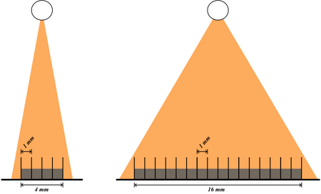
Left, 4-row MDCT; Right, 16-row MDCT. Both have the same detector size (1 mm) but different total detector widths (4 mm and 16 mm, respectively).
The total detector width is equal to the thickness of each detector row multiplied by the number of rows; the thickness of each row determines the z-axis resolution of the scan. (Again, the z-axis resolution of the images is determined by the reconstructed slice thickness and, to some degree, pitch, as described in the section on helical CT.)
Prospective ECG Triggering
|
Heart Rate: Scanner Type: |
Simulation of prospective ECG-gated cardiac CT technologies. Top, ECG tracing; shaded blue denotes the times when the scanner tube is turned on. Gray line denotes the current time. Bottom, illustration of the scanner gantry position and cumulative imaging coverage (shaded blue), while the heart beats.
The simplest technology for acquiring gated cardiac images is referred to as prospective gating or sometimes prospective ECG triggering. In this mode, the scanner monitors the patient's ECG. It is set to scan at a particular point in the cardiac cycle, which is typically in diastole since the heart is moving the least then. The scanner interprets the ECG and determines a delay after the QRS complex to begin scanning. At that point, the ECG triggers the scanner to start scanning. As described in the section on CT physics, the scanner must complete a 180 degree rotation in order to obtain a full image. It then waits for the next diastolic phase to scan the next part of the heart. For this reason, some people refer to this technique as "step and shoot," since the scanner moves the table in between successive diastolic phases.
Each scan has a certain z-axis coverage, which is determined by the width of the CT detector and pitch. To complete the cardiac CT, we need to cover the entire heart, which is typically around 12-15 cm. Thus, with wider detectors (more rows), the heart is captured in fewer beats. The problem with needing multiple beats is that the patient may move in between the beats; if the scan is really slow, the patient may even breathe which will change the position of the heart in the chest and make the scan uninterpretable.
Heart Rate. Heart rate is critically important to cardiac CT since this determines the required temporal resolution. In particular, as you may remember from cardiac physiology, the length of systole is pretty constant over varying heart rates; the diastolic interval changes to adjust the heart rate. As we mentioned, the best CT images are typically obtained in diastole, since that is when the heart is moving least. In faster heart rates, there is less time for diastole. As a rule of thumb (per Mahesh and Cody), for heart rates up to 75 bpm, the diastolic interval lasts around 250 ms. For heart rates closer to 100 bpm, there is only around 100 ms for diastole.
The time required to obtain diagnostic data is the time to rotate the tube 180 degrees (plus fan angle); this turns out to be just slightly greater than half the tube rotation time (i.e. the time for the tube to rotate 360 degrees around the patient). Increasing tube rotation time is an engineering challenge principally because of the gantry weight, which exerts very strong 'g-forces' (centrifugal forces) on the gantry ring. Presently, the fastest CT scanners have a rotation time around 300 ms. Thus, the 'temporal resolution' or 180+fan time is around 180 ms - and therefore, heart rates in the 80s are the highest for which prospective gating can obtain motionless images.
Ultrahigh Pitch. Recently, dual-source CT scanners have been developed. These scanners have two x-ray tubes (sources) and two detectors within the gantry, spaced at a 90 degree angle. This means that the tube needs only rotate 90 degrees to obtain a full data set, instead of 180 degrees (the two tubes contribute 90 degrees each to make 180 degrees of data from only a 90 degree rotation). This allows the scanner to use a much higher pitch to scan the patient and thus gives a greater z-axis coverage in the same amount of time.
|
Detector size: 0.7 mm Number of Detector Rows: |
Pitch |
Coverage in 90 degrees rotation cm Coverage in 180 degrees rotation cm |
The ultrahigh pitch scan is thus able to cover the entire heart in a single rotation by its expanded z-coverage. Additionally, since the data for any slice is obtained from only a 90-degree rotation, the temporal resolution for a slice is substantially better (since it's only 1/4 of the tube rotation time, instead of 1/2). This improves motion artifacts within the slice as well.
Cone Beam CT. An alternative approach to dual-source CT to cover the entire heart in a single beat is an especially wide detector width. Recently, Toshiba has developed a detector with 320 rows of 0.5 mm detectors, for a total detector width of 16 cm, enough to cover the entire heart. This scan is actually performed in axial (i.e. non-helical) mode, since no table movement is necessary.
The challenge with wide detectors is that the x-ray beams can no longer be thought of as imaging successive slices (like a stack of coins) - the 3D nature of the beam must be taken into account. This is often referred to as a cone-beam geometry, although it really looks more like a pyramid:

Illustration of the cone-beam CT geometry. Left, the pyramidal shape of the beam seen from an angle, with the z-axis of the patient denoted by the black line. Right, side-on view showing how the detectors at the edges perceive an x-ray path that spans multiple z-axis positions within the patient, while detectors at the center are pretty much in a single slice.
You can see from the figure that as the detectors become spread farther out along the z-axis, they no longer represent data from a single slice. X-ray paths that travel from the tube to those detectors span multiple slices. This requires a much more complicated reconstruction algorithm which can understand the 3-dimensional relationship. Of note, while we referred to the 320-row detector as a cone beam, in fact most modern MDCT systems require a cone-beam reconstruction algorithm (starting around 64 rows). However, much of the literature reserves the term 'cone beam CT' for those scanners with a very large detector width.
Retrospective ECG Gating
|
Heart Rate: Pitch: Reconstruction Mode: |
Simulation of retrospective ECG gating (reconstructing a diastolic stack). Top left, ECG tracing with gray line denoting the current time. The tall shaded blue boxes denote the portions of diastole used for reconstruction; their width is determined by the gantry rotation time. The shorter shaded blue line is continuous - showing that the tube is on during the entirety of the scan. Bottom left, plot of the scanner position along the z-axis of the patient over time; again shaded blue denotes the portions used for reconstruction of diastole. Dashed lines show any gaps or overlap in z-axis coverage (between successive diastoles). Bottom right, illustration of the heart with current tube position denoted by the blue line and gantry helix displayed as gray lines; as an entire detector width is completed, that region is shaded in blue.
As an alternative to prospective gating, retrospective gating was developed. This technique scans the patient continuously, although only certain portions of the scan are used to reconstruct the image. Because the scan spans all phases of the cardiac cycle, we can reconstruct images in systole, diastole, or anywhere in between. This can be useful to obtain functional information and can also be helpful in patients where there is still some motion during portions of diastole, since we can pick slightly earlier or later phases to use for the reconstruction.
Pitch. Retrospective gating requires very low pitch, < 1, in order to cover all portions of the heart during all phases. A pitch of less than 1 allows for overlapping the helical coverage so that each point along the z-axis can have continuous coverage. Because MDCT detectors have width, even within one helical cycle, points are covered continuously (i.e. by adjacent detectors). The required pitch depends on the rotation time of the gantry in relationship to the R-R interval of the patient. We need to ensure that by the time the next diastolic phase of the cardiac cycle occurs, the scanner has just reached a new area of z-axis coverage. The faster the heart rate, the faster we need to move to arrive at the next z-axis point at the next diastole - in other words, the faster the heart rate, the faster the pitch.
You can see in the simulation above how altering pitch causes gaps or overlap in z-axis coverage. The plot in the bottom left shows the portion of the z-axis that is adequately covered for a certain cardiac phase (in this case, diastole). On the right, you can see how the tube position is changing over time. The tube makes a very tight helix around the patient, covering many areas multiple times; but by the time the next diastolic phase occurs, the tube is exactly 1 detector width over. Again, we need 180 degrees of coverage for each phase of the cardiac cycle in order to reconstruct CT images.
Because of the low pitch, retrospective gating yields a very high radiation dose (we are covering each part of the chest many times). As noted in the section on helical CT, radiation dose is inversely proportional to pitch. Temporal resolution is also an issue with retrospective gating. We must be able to cover the diastolic phase in one tube rotation (well, the time for 180 degrees rotation) in order for the reconstructed image to be motionless. Even though we can reconstruct at any desired phase, the time window the reconstruction is still limited by the tube rotation speed.
Partial Scan versus Multiple Segment Reconstruction. In order to solve the temporal resolution problem, multiple segment (sometimes called multisegment) reconstruction was developed. In the discussion above, we described what is known as partial scan reconstruction. In this mode, each phase of the cardiac cycle is reconstructed by a contiguous 180-degree tube rotation. The temporal resolution is determined by this time, and the pitch is adjusted so that the tube is ready for the next z-axis coverage by 180-degree rotation when the next diastole occurs. In multiple segment reconstruction, the 180-degree coverage is split among successive heartbeats. For example, with 2 segments, we can acquire 90 degrees of data from one heartbeat and the other 90 degrees from the next heartbeat. The advantage is that now our temporal resolution is cut in half (we can scan a diastole in half the time per beat - although we need twice as many heartbeats).
Multisegment reconstruction requires a lower pitch than partial-scan reconstruction. Since it's used mostly for faster heartbeats, though, the pitch will likely be similar when compared to partial-scan for a low heart rate (i.e. pitch for partial-scan at 60 bpm is similar to pitch for multi-segment for 100 bpm). The disadvantage of multi-segment reconstruction, besides the higher radiation dose associated with lower pitch, is that we need to average across multiple heart beats. If there is motion of the patient (e.g. respiration) or heart (e.g. changing R-R interval so our cardiac phase is slightly off), then the images will be blurred.
Comparison of Prospective and Retrospective Techniques
Temporal Resolution. The major determinant of temporal resolution is scanner rotation speed in either technique. However, as we mentioned, using multi-segment reconstruction in retrospective gating gives you twice as good temporal resolution. Alternatively, using a dual-source scanner gives you twice as good temporal resolution because you can reconstruct data with only a 90-degree tube rotation.
Temporal Flexibility. Prospective gating suffers from the fact that data is only acquired at pre-determined phases of the cardiac cycle. Patient with irregular heartbeats or even a single PVC can make sections of the heart entirely uninterpretable. Additionally, if there is a bit of motion in a portion of the acquired diastole, you are stuck with the data you have. Finally, you are unable to obtain functional information about the myocardium. Retrospective gating solves these problems by obtaining data continuously; incorrectly binned data can be 'edited out' (to some degree, depending on how long, etc.). The heart can be reconstructed in early diastole, late diastole, or systole to attempt to obtain less motion in different regions of the heart. Finally, since an entire movie was obtained of the heart, we can calculate function and evaluate wall motion.
Radiation Dose. Radiation dose in CT is discussed in much more detail elsewhere. In regards to cardiac CT, the main issue is the pitch. For prospective gating, the scan is equivalent to a routine chest CT. However, for retrospective gating, since we must use very low pitch scans to cover the entire heart during all cardiac phases, our dose goes up. Typical pitch ranges from 0.2 to 0.4, which represents dose increase of 3-6 fold versus a pitch of 1.2 (more typical for routine CT).
ECG Dose Modulation. As a compromise between the radiation savings of prospective gating and the temporal coverage of retrospective dating, recently scanner companies have developed ECG dose modulation. In this technique, the scanner performs retrospetive gating. However, to save radiation dose, the tube current is turned down during systole. Thus, images of the heart during systole are very noisy but still diagnostic. Images during diastole are obtained at the full radiation dose for better evaluation of structures such as the coronary arteries. This technique can yield dose savings of up to 65%.
References
- Mahesh M and Cody DD. "Physics of Cardiac Imaging with Multiple-Row Detector CT." Radiographics 27(5).
- Litmanovich, et al. "Dose Reduction in Cardiothoracic CT: Review of Currently Available Methods." Radiographics 34(6).
- Flohr T and Ohnesorge B. "Cardiac Gating." in Integrated Cardiothoracic Imaging with MDCT. M. Remy-Jardin and J Remy, ed. 2009 (Springer).
- Flohr TG, et al. "Dual-source spiral CT with pitch up to 3.2 and 75 ms temporal resolution: Image reconstruction and assessment of image quality." Med. Phys. 36 (12). Pubmed. (Technical article)
Content, images, and simulations copyright 2014 Mark Hammer. All rights reserved.