X-Ray Physics: Magnification and Collimation in Radiography
This simulation illustrates the effects of changing various settings on a fluoroscopy or radiography (x-ray) system on image quality and patient dose. Note that it does not take into account factors such as kV, filtering, anti-scatter grid, patient thickness, or patient anatomy. Detector resolutions are ballpark figures taken from the literature for CR, DR, or fluoroscopy systems. If your browser does not support Java, use the Presets to see examples of how the detector setup and image change.
Dose in Radiography and Fluoroscopy
It's probably worthwhile to start with a brief overview of what dose means and why we measure it. Dose represents the amount of energy deposited in tissue from (any type of) radiation per mass of tissue, and is measured in J/kg = Gray (Gy). Note that because it is energy per unit mass, depositing 1 Joule of energy in a 1 kg foot is the same dose as depositing 15 J to the abdomen, which weighs about 15 kg. In CT, we take this into account by multiplying the CTDI by the length of the scan to obtain a dose-length product or DLP. In radiography, we can take this into account by multiplying the dose by the area irradiated to get a dose-area product or DAP (measured in mGy*cm2).
In fluoroscopy, often for ease of measurement, instead of measuring dose in tissue, the machine can measure the air kerma which stands for Kinetic energy released in matter (specifically, air). Thus, the unit may report an air kerma and kerma-area-product. Many fluoroscopy units, especially those used for interventional procedures, will report an air kerma at the 'interventional reference point,' often abbreviated as Kar. The interventional reference point is a point along the beam 15 cm towards the x-ray source (which typically lies below the table). This represents the most common position of the table (and thus the skin on the patient's back). Kerma in air can be converted to dose of soft tissue using lookup tables. Finally, exposure represents the electric charge created in a tissue or the detector from radiation; this is often used when describing factors related to the image receptor.
What measure is most relevant? There are two types of adverse consequences of radiation: the deterministic and the stochastic effects. Deterministic effects relate to direct killing of cells by radiation and include (at relevant doses) skin erythema, depilation, and ulceration/necrosis. Stochastic effects relate to genetic damage of cells that can lead to cancer down the line. Importantly, deterministic effects relate directly to the amount of radiation a single cell receives; these require a large dose to become apparent. Stochastic effects can occur (randomly) with very small doses, and even one cell can turn cancerous. Deterministic effects are thus best measured by the total dose to a particular patch of skin; stochastic effects are best related to the total amount of radiation deposited in the body. Therefore, dose is a better measure of deterministic effects and dose-area product is a better measure of stochastic effects. As noted above, many fluoroscopy units report Kar, which provides a metric for the entrance skin dose and thus likelihood of deterministic effects (e.g. skin necrosis).
Geometry
Similar to a lens in photography, where the patient is positioned relative to the source and detetor changes magnification and field of view (see simulation above). Three terms are used to describe positioning: source-object distance (SOD, where the object represents the patient); object-image distance (OID, where the image is the detector); and source-image distance (SID). The effects of moving the patient and detector can be seen by the method of similar triangles.
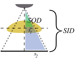
As the patient is brought closer to the detector (decrease OID), magnification decreases. Similarly, parallax, which means how objects at different depths in the patient are skewed on the image, also decreases. Increasing SOD similarly decreases magnification. This can be easily seen if you imagine how the x-ray rays become more parallel as the source is moved farther and farther off. Alternatively, as the OID is increased, magnification increases.
Dose. Generally, we need a certain amount of radiation (exposure) to reach each point on the x-ray detector. (This amount depends on the type of detector and, in the case of now-obsolete film, the speed of the film.) This is in order to ensure good signal-to-noise in the image. If we increase the magnification, that means a given amount of anatomy is spread out over a larger area on the detector. Thus, there is less radiation per pixel and the image would be too dark. In order to avoid this, the amount of radiation has to be increased. In order to compensate for a smaller area of anatomy, we need to increase the dose by the magnification squared because area = height * width.
This can result is a substantially higher radiation dose to the irradiated tissue - but notice that the area of irradiated tissue is smaller! Indeed, the DAP does not change at all (because the amount of radiation increase is equal to the area decrease). So, we can interpret that by using magnification, we are exposing the patient to a greater risk of deterministic sequelae such as skin necrosis but an equivalent risk of stochastic sequelae.
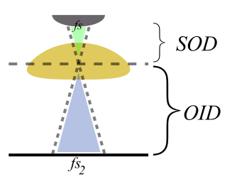
Blur. Because x-rays come from a spot, not a point, on the anode, there is some smudginess in the picture produced. The x-rays originating from slightly different spots on the anode take slightly different angles to hit the same point on the detector. This blurring is sometimes referred to as penumbra. Focal spot blur can get magnified by poor geometry (decreasing SOD), as seen below:
In addition to focal spot blur, patient motion can also produce blur. Whenever a part of the patient's anatomy is magnified by geometry, patient motion is magnified by the exact same amount. In addition, magnification modes often require use of a smaller focal spot (to reduce focal spot blur, which is worse with magnification). Smaller focal spots have a lower (anode) heat capacity and thus require longer exposures because they have a lower mA limit (so for the same mAs, they require a longer exposure). With longer exposures, patient motion can be an even bigger problem.
Collimation. Collimation is a great tool in radiography and fluoroscopy. It provides two advantages: (1) reduced DAP and (2) reduced scatter. The DAP is reduced for obvious reasons - the area irradiated is decreased; the dose itself won't change. Because radiating any part of the body produces scatter photons that can head off in different directions - including towards the detector at odd angles - if you decrease the amount of irradiated body, you decrease scatter. Scatter from neighboring body parts can hit the detector underneath where you are trying to image, so if you collimate, you clean up the image where you are looking; for more details, see the discussion on SNR.
Detector Electronic Magnification
Instead of using geometric magnification, you can magnify the image itself that your detector receives. This is really only relevant in fluoroscopy, where you have dynamic access to an electronic detector. The mechanism of magnification depends on the type of detector, be it flat panel detectors (FPD, the current standard) or image intensifier (II, which are being phased out). Details of how these systems work and how they produce magnification can be found in the references below. (Often, flat-panel displays will turn off pixel binning, among other things.) However, it is important to know that similarly to geometric magnification, electronic magnification requires increased dose. Two differences are important to note between geometric and electronic magnification: (1) focal spot blur is not increased with electronic magnification and (2) in the case of flat-panel detectors, electronic magnification does not require as much dose increase. Again, the dose delivered to a portion of the patient's skin will increase; however, the DAP may or may not increase (or may not increase as much) as with geometric or positional magnification.
References
- Mahesh M. "Fluoroscopy: Patient Radiation Exposure Issues." Radiographics July 2001. 21(4).
- Nickoloff EL. "Survey of Modern Fluoroscopy Imaging: Flat-Panel Detectors versus Image Intensifiers and More." Radiographics March 2011. 31(2).
- Mahesh M. "Challenges in Evaluating Flat-Panel Detector Fluoroscopy Systems." J Am Coll Radiol. Mar 2013 10(3). Pubmed.
- Poletti JP and McLean D. "The effect of source to image-receptor distance on effective dose for some common X-ray projections." Br J Radiol. 78 (2005). Pubmed.
DopplerSim Applet copyright 2014 Mark Hammer. All rights reserved.